 |
|
We deal in five types of C.I. PIPES. Below are some small details on them.
|
|
|
TOLERANCE ON LENGTH :
| Socket and Spigot Pipes |
= |
± |
100 mm |
| Plain ended Pipes |
= |
± |
100 mm |
| Flanged Pipes |
= |
± |
10 mm |
TOLERANCE ON MASS :
| Socket and Spigot Pipes |
= |
± |
5 percent |
|
|
 |
 |
| Table 1 : DIMENSION OF SOCKETS AND SPIGOTS OF PIPES (LEAD JOINT) |
 |
Nominal
Diameter
DN |
Barrel |
S O C K E T D I M E N S I O N S |
Joint
Thickness |
 |
 |
 |
| DE |
DI |
P |
g |
h |
a |
K |
L |
M |
N |
f |
| |
|
|
Min |
Min |
Optional |
|
|
|
|
|
 |
| 80 |
98 |
116 |
84 |
22.5 |
10.0 |
3.0 |
8.5 |
9 |
14 |
3 |
9.0 |
| 100 |
118 |
137 |
88 |
23.0 |
10.5 |
3.0 |
8.5 |
9 |
14 |
3 |
9.5 |
| 200 |
222 |
241 |
100 |
26.0 |
13.0 |
3.0 |
8.5 |
12 |
17 |
3 |
9.5 |
| 400 |
429 |
449 |
110 |
32.0 |
18.0 |
3.5 |
8.5 |
15 |
20 |
3 |
10.0 |
| 750 |
790 |
813 |
123 |
42.5 |
27.0 |
4.0 |
8.5 |
25 |
28 |
3 |
11.5 |
| 1050 |
1124 |
1143 |
128 |
52.0 |
36.0 |
5.0 |
8.5 |
28 |
32 |
3 |
12.0 |
 |
|
|
|
|
 |
| |
|
| |
 |
| Table 2 : DIMENSION OF SOCKETS AND SPIGOTS OF PIPES (PUSH-ON JOINT) |
 |
Nominal
Diameter
DN |
Barrel |
S O C K E T D I M E N S I O N S |
|
|
| DE |
X |
DI |
P |
Q |
I |
J |
K |
N |
O |
S |
T |
L |
M |
| |
Min |
|
|
|
|
|
|
|
|
|
|
|
Min |
 |
| 80 |
95 |
9 |
99.0 |
89 |
52 |
121.0 |
116.0 |
102 |
12 |
5.5 |
5.0 |
4.0 |
3.0 |
10.8 |
| 100 |
115 |
9 |
119.0 |
92 |
52 |
141.0 |
136.0 |
122 |
12 |
5.5 |
5.0 |
4.0 |
3.0 |
11.3 |
| 200 |
219 |
9 |
223.0 |
102 |
60 |
248.0 |
242.0 |
226 |
15 |
6.5 |
6.0 |
5.0 |
3.5 |
14.0 |
| 400 |
426 |
14 |
431.5 |
112 |
74 |
461.0 |
454.0 |
435 |
19 |
9.0 |
8.0 |
5.0 |
4.5 |
19.4 |
| 750 |
787 |
15 |
795.0 |
143 |
91 |
834.0 |
827.0 |
797 |
21 |
11.0 |
10.0 |
5.0 |
5.0 |
27.0 |
| 1050 |
1118 |
19 |
1125.0 |
143 |
91 |
1165.0 |
1161.0 |
1134 |
23 |
12.0 |
11.0 |
6.0 |
6.0 |
32.0 |
 |
|
|
|
|
 |
| |
|
| |
 |
| Table 2 : DIMENSION OF SOCKETS AND SPIGOTS OF PIPES (PUSH-ON JOINT) |
 |
Nominal
Diameter
DN |
Barrel |
S O C K E T D I M E N S I O N S |
|
|
| DE |
X |
DI |
P |
Q |
I |
J |
K |
N |
O |
S |
T |
L |
M |
| |
Min |
|
|
|
|
|
|
|
|
|
|
|
Min |
 |
| 80 |
95 |
9 |
99.0 |
89 |
52 |
121.0 |
116.0 |
102 |
12 |
5.5 |
5.0 |
4.0 |
3.0 |
10.8 |
| 100 |
115 |
9 |
119.0 |
92 |
52 |
141.0 |
136.0 |
122 |
12 |
5.5 |
5.0 |
4.0 |
3.0 |
11.3 |
| 200 |
219 |
9 |
223.0 |
102 |
60 |
248.0 |
242.0 |
226 |
15 |
6.5 |
6.0 |
5.0 |
3.5 |
14.0 |
| 400 |
426 |
14 |
431.5 |
112 |
74 |
461.0 |
454.0 |
435 |
19 |
9.0 |
8.0 |
5.0 |
4.5 |
19.4 |
| 750 |
787 |
15 |
795.0 |
143 |
91 |
834.0 |
827.0 |
797 |
21 |
11.0 |
10.0 |
5.0 |
5.0 |
27.0 |
| 1050 |
1118 |
19 |
1125.0 |
143 |
91 |
1165.0 |
1161.0 |
1134 |
23 |
12.0 |
11.0 |
6.0 |
6.0 |
32.0 |
 |
|
|
|
|
|
TOLERANCE :
| Tolerance on length |
: |
± |
10 mm |
| Tolerance on mass |
: |
± |
5 percent |
HYDROSTATIC TEST :
For Hydrostatic Test, the Pipes are kept under pressure for 15 seconds. They are struck moderately with a 700 gm hammer, withstanding the pressure test without showing leakage, sweating or other defect of any kind. |
|
 |
 |
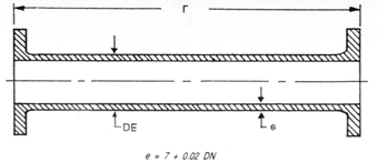
| Table 5 : FLANGED PIPES SAND CAST — CLASS - B |
 |
Nominal
Diameter
DN |
Barrel outside
Diameter |
Barrel
Thickness |
Mass/mtr.
(Barrel) |
Mass/Flange |
Mass of Pipe including
two Flanges (App.) |
 |
 |
 |
 |
 |
| DE |
e |
(App.) |
(App.) |
1 mtr. |
2 mtr. |
2.75 mtr. |
 |
| 80 |
98 |
8.6 |
17.3 |
3.7 |
24.7 |
42.0 |
55.0 |
| 100 |
118 |
9.0 |
22.0 |
4.2 |
30.4 |
52.4 |
68.9 |
| 200 |
222 |
11.0 |
52.1 |
9.3 |
70.7 |
122.8 |
161.9 |
| 400 |
429 |
15.0 |
139.5 |
23.4 |
186.3 |
325.8 |
430.4 |
| 750 |
790 |
22.0 |
380.6 |
69.8 |
520.2 |
900.8 |
1186.3 |
| 1500 |
1567 |
37.0 |
1333.1 |
276.2 |
1885.5 |
3214.6 |
4218.4 |
 |
|
|
|
|
|
TOLERANCE :
| Tolerance on length |
: |
± |
10 mm |
| Tolerance on mass |
: |
± |
5 percent for DN 200 & above |
| |
|
+ |
8 percent for DN upto 150 |
| |
|
– |
5 percent for DN upto 150 |
The standard working length of Pipes is 2.75 mtr. long (9 feet approx.) uto 600 mm dia and 2 mtr. long above 600 mm dia.
HYDROSTATIC TEST :
Pipes are tested hydraulically to prevent leakage, sweating or other defects of any kind. The pressure is applied internally, and steadily maintained for a period of 15 seconds, when pipes are struck moderately with a 700 gm. hammer. |
|
 |
 |
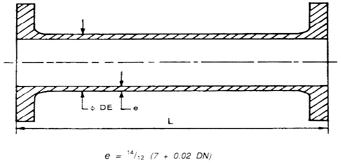
| Table 6 : SIZES AND MASS OF DOUBLE FLANGED PIPES |
 |
Nominal
Diameter
DN |
Barrel outside
Diameter |
Barrel
Thickness |
Mass/mtr.
(Barrel) |
Mass/Flange |
Mass of Pipe including
Flanges (App.) |
 |
 |
 |
 |
 |
| DE |
e |
(App.) |
(App.) |
1 mtr. |
2 mtr. |
2.75 mtr. |
 |
| 80 |
98 |
10.0 |
19.8 |
3.7 |
27.2 |
47.0 |
61.9 |
| 100 |
118 |
10.5 |
25.4 |
4.2 |
33.8 |
59.2 |
78.3 |
| 200 |
222 |
12.8 |
60.1 |
9.3 |
78.7 |
138.8 |
183.9 |
| 400 |
429 |
17.5 |
162.6 |
23.4 |
209.4 |
372.0 |
494.0 |
| 750 |
790 |
25.6 |
443.8 |
69.7 |
583.2 |
1027.0 |
1359.9 |
 |
|
|
|
|
|
TOLERANCE :
| Tolerance on length |
: |
± |
10 mm |
| Tolerance on mass |
: |
± |
5 percent for DN 200 & above |
| |
|
+ |
8 percent for DN upto 150 |
| |
|
– |
5 percent for DN upto 150 |
The standard working length of Pipes is 2.75 mtr. long (9 feet approx.) uto 600 mm dia and 2 mtr. long above 600 mm dia.
HYDROSTATIC TEST :
Pipes are tested hydraulically to prevent leakage, sweating or other defects of any kind. The pressure is applied internally, and steadily maintained for a period of 15 seconds, when pipes are struck moderately with a 700 gm. hammer. |
|
 |
 |
| Table 6 : SIZES AND MASS OF DOUBLE FLANGED PIPES |
 |
Nominal
Diameter
DN |
Barrel outside
Diameter |
Barrel
Thickness |
Mass/mtr.
(Barrel) |
Mass/Flange |
Mass of Pipe including
Flanges (App.) |
 |
 |
 |
 |
 |
| DE |
e |
(App.) |
(App.) |
1 mtr. |
2 mtr. |
2.75 mtr. |
 |
| 80 |
98 |
10.0 |
19.8 |
3.7 |
27.2 |
47.0 |
61.9 |
| 100 |
118 |
10.5 |
25.4 |
4.2 |
33.8 |
59.2 |
78.3 |
| 200 |
222 |
12.8 |
60.1 |
9.3 |
78.7 |
138.8 |
183.9 |
| 400 |
429 |
17.5 |
162.6 |
23.4 |
209.4 |
372.0 |
494.0 |
| 750 |
790 |
25.6 |
443.8 |
69.7 |
583.2 |
1027.0 |
1359.9 |
 |
|
|
|
| |
|

